EYTraker V11 LTE: 27 August 2026
Introduction
In order to improve the functionality and the user
experience of the EYTraker the unit has undergone a major long overdue upgrade.
The
latest revision of the EYTraker V11 retains the reliable SIMCom
Cat 1 LTE/GPS engine A7670E module that is available from Makerfabs or Robotics as a complete voice and data LTE
solution. The new unit features a dual core ESP32S3 processor with power and
battery management included. The design remains compatible with Arduino IDE that
makes it ideal to use in a familiar development environment. By using the Espressif online flash utility the downloaded .bin files can be flashed onto the
ESP32S3 boards with no more need for compiling of the source code. The unit
retains LTE or 4G capability that increases the tracking reliability of the
unit with the most significant upgrade being the use of the Wi-Fi function or USB configuration software on the ESP32S3
to allow for remote and/or local Wi-Fi management through a dedicated W-Fi Access
Point, home Wi-Fi connected webpage, USB configuration or over the newly
developed remote management software that can also be found on the download site.


The
features of the EYTraker V11 remains the same as V9 with additional features
the includes the following:
·
Local
Wi-Fi AP configuration
·
Wi-Fi
configuration via your home network
·
USB
configuration via the configuration app
·
Remote
configuration over the air with the APRS Bridge software
·
Robust
WDT protected firmware
Similar to the V9, the design of the EYTraker V11 is
based on off-the-shelf components that allows for quick configuration of the
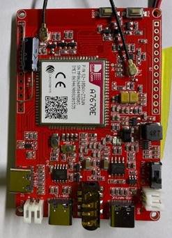
unit. The basic design is based on the A7670E module PCB and a LM2595 buck
boost converter set to 5V feeding the USB-C or JST-PH connector. A small 3.8V 800mA
LiPo battery provides about 2 hours of backup power in case of a power
disconnect. The ignition sense with a voltage divider (220K and 1M resistors) and
smoothing cap (1 uF) on pin IO1. The 220k resistor
and 1uF capacitor is placed between GND and IO1 with the IGN voltage via the 1M
resistor to pin IO1. The buck boost used in the pictures is a Mini360 set to
5V.


A
very simple design supported by stable firmware on the ESP32S3 that has been
tested extensively.
The
unit is housed in a plastic enclosure (110mm (L) x 60mm (W) x 24mm (H)) with an
external power connector, GPS SMA pigtail and GSM SMA pigtail to allow the
connection of external GPS and GSM antennas. The option exist
to use an internal GPS antenna if required. The complete unit draw 80 mA on
average with the Wi-Fi radio switched off in the configuration.

There
are 2 options available to flash the ESP32S3 module:
Option
1: Custom EYTraker Flashing tool:
·
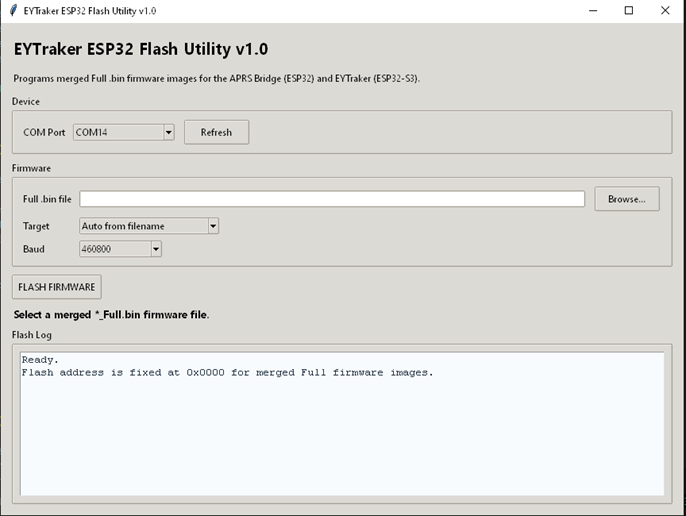
The
.bin full firmware can be downloaded and flashed with the EYTraker
Flashing utility also located in the download section. Both the executable file
and the Python source code is available. The executable will be flagged by MS
SmartScreen but click on More info and run anyway. The other option is to run
the Python code on Visual Studio Code with the correct libraries installed.
·
Connect
the ESP32S3 Tracker board to the PC with the cable plugged into the USB port.
If the CP2102 drivers are not loaded on your PC, you will have installed then.
Without the drivers the COM port will not show up, and the port will be flagged
as unknown in the Device Manager of you Windows
machine.
·
Refresh
the Flash tool Com port and select the ESP32S3 Com port.
·
Browse
and load the EYTracker V11 Full.bin
file that has been downloaded previously and the flash utility will auto select
the ESP32S3 in the target window, make sure this is the case. Leave the Baud
rate at 460800.
·
Click
on the FLASH FIRMWARE button on the flash utility and confirm the installed
progress in the status window.
·
When
done, reboot with the slider switch and look for the EYT-Config-NOCALL Wi-Fi
Access point (password: eytraker123) and connect to IP address 192.168.4.1 or
connect the via the USB configuration application also on the download page.
·
From
one of these configuration pages, you can activate the home Wi-Fi option and
configure the unit further.
·
The
home W-Fi IP address will be on your home router configuration screen or on the
USB config app when you read the tracker back after activating the home Wi-Fi
option.
·
Once
you have the unit up and running it is advisable to load the latest firmware
via the Elegent OTA function on the config page. This
.bin fil is also available in the download section. Sometimes the initial
firmware and the new firmware are not the same revision.
Option 2: Espressif Online tool (more
reliable than the ESP32):
·
The
.bin full firmware can be downloaded and flashed with the Espressif online
utility.
·
Connect
the ESP32S3 tracker board to the PC with the cable plugged into the USB TTL
port.
·
When
the online flash tool website has loaded click on Connect and switch on the
tracker board.
·
The
COM port will become available in the dialog window, select it and click
connect. The Flash address is 0x0000 and select the v11.21 ESP32S3 FULL.bin file that you have downloaded and click
program.
·
The
firmware will be flashed onto the tracker. When done, reboot with the slider
switch and look for the EYT-Config-NOCALL Wi-Fi Access point (password:
eytraker123) and connect to IP address 192.168.4.1 or connect the via the USB
configuration application also on the download page.
·
From
one of these configuration pages, you can activate the home Wi-Fi option and
configure the unit further.
·
The
home W-Fi IP address will be on your home router configuration screen or on the
USB config app when you read the tracker back after activating the home Wi-Fi
option.
·
Once
you have the unit up and running it is advisable to load the latest firmware
via the Elegent OTA function on the config page. This
.bin fil is also available in the download section. Sometimes the initial
firmware and the new firmware are not the same revision.
You
will have to change the unit callsign, SSID and icon based on your requirements
and insert a suitable LTE simcard for one of the
South African cell phone network providers. Telkom and CellC
has not been tested. Also ensure that the GSM and GPS antennas as connected.
The
unit connects to the South African APRS-IS server at http://www.aprs-za.com:14501 with full position reports and engineering
data available at aprs.fi.
Please
send me an email if there are any questions or you can’t get the firmware
to flash or having other issues.